

The watermill history
Il Mulino di Posara is also known as Il Grande Mulino. There are two watermills within the complex, one built around the 17th century and the other in the 19th. The ruins of a third, even earlier, mill stand beside the millrace, 100 metres or so upstream.
The Rosaro (a torrente rather than a fiume, that is a torrent rather than a river) sweeps round the mills.
The Old Mill is the lower, downstream part of the complex and is of the 'Greek', 'Scandinavian' or a ritrecine type (a ritrecine was a Roman sweep-net) with a horizontal water wheel. No precise date has yet been put on its construction of the three-storey building, but it is believed to originate from the 17th Century (seicento).
Just above the Old Mill the millstream divides into four small channels made of oak. (All wooden parts of the mill in contact with water are made of oak.) These wooden channels, or mill-races, carry the water to a space beneath the Old Mill, which is divided into four vaulted galleries, one for each of the mill races. The gallery nearest the river merges with the one next to it, so that there are just three arched openings through which the water falls into the arched exit that takes it back to the river.
The lower parts of the second and third millstones still retain their wooden shafts and horizontal water wheels, but the shafts and paddle wheels corresponding to the first and fourth millstones are not to be found and the channel for the first millstone has been blocked off.
How it works
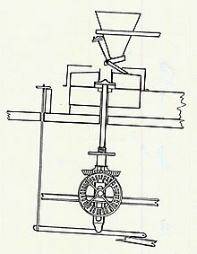
Drawing 1
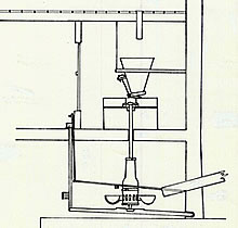
Vertical cross section through millstone and related machinery in Mill 1
The water from the oak channel falls directly on to the paddles (or spoons) of the horizontal water wheel. The wheel is mounted on a wooden shaft, which is reinforced with iron bands. The shaft rises through the floor above, then through the fixed lower millstone, and is fixed to the upper movable millstone. You can raise or lower the upper millstone to regulate the grinding pressure. It's also possible to divert the flow of water away from the paddles to stop the wheel's movement.
Of the four millstones, the first three (nearest the stairs) were for chestnuts and acorns. The fourth is for wheat. (By substituting the upper stone, it was also possible to grind maize.) The millstones for grinding chestnuts were made of sandstone from the quarry at Pognana; those for wheat were made of limestone and those for maize were made of a hard, flinty stone.
The millstones have a diameter of 1.3 metres and had four grooves passing from the centre where the flour collected and was then carried towards the outer rim of the millstone
From time to time it was necessary to re-dress the grinding surface of the millstones, using a chisel-headed hammer. During the grinding of chestnuts encrustations tended to form, due to damp or insufficiently-dried chestnuts. To remove these deposits the upper millstones were lifted with rollers so that they could be cleaned.
Above each millstone was a hopper, a type of wooden funnel, which was filled with the corn or chestnuts to be milled. A rudimentary valve worked by a cord regulated the amount of material entering the millstone and a small bell attached to the hopper rang when it was empty. A piece of wood touching the moving millstone transmitted a small vibration to the hopper to help the grains fall better.
The hoppers were filled with grain or chestnuts through holes in the floor of the room above.
The flour was put into sacks by hand as it collected in the space around the millstones and was then taken into the open space outside the working area.
In historical times thee was a fifth millrace leading back upstream to a hemp mill in a room underneath what is now Mill 2. This, too, is of the a ritrecine type. The diameter of this millstone was approximately 85cm, larger than that for grain or chestnuts.. It was used to crush hemp which was then taken home by the women of the neighbourhood for spinning and weaving into fabric on their looms.
The hemp mill was in use until about 1920. Today only the wooden channel is visible, its upper part walled up: of the water wheel and its mechanism, no trace remains
The late Signor Alderico Alderici believed that this part of the mill goes back about 100 years, because it was built by his father. The upper part of the millstone area is similar to that of the Old Mill, with four millstones placed one next to the other; but the filling of the hoppers takes place at the millstone level, since another floor was not built above this area.
Two millstones were used for grinding chestnuts: they have not been used since 1940, when the 'chestnut disease' attacked the trees in this area. At the moment one of these two is without the upper millstone. Both have the gears to the drive shaft disconnected and the arm which raises and lowers the millstone is blocked.
The two other millstones are complete, theoretically, able to function. Millstone number three (as seen from the old mill) was for maize and was working regularly until 1989, having been used for the personal needs of the Alderici family. Bill and Lois have undertaken some restoration work on this wheel but it is not at present fully operational. The fourth millstone was for wheat.
The millstones for chestnuts ground approximately 1000 quintale (a quintale is 100kg) in four months work; if the chestnuts were perfectly dry it was possible to obtain around half a quintale of flour per hour, corresponding to 10 to 15 quintale a day. The maize millstone produced around one quintale of flour per hour and the same quantity was produced by that for wheat.
There is a fireplace In the corner of the millstone area which, as in the old mill, was used to warm the workers at night. In front of the fourth millstone there was the pesa (weighbridge) for the wheat, connected by a tube to the cylinder mill.
How it works
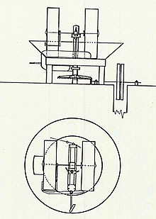
Drawings 2 & 3
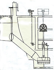
(Left) Vertical cross section of turbine and principal driving mechanisims in Mill 2
(Right) Vertical cross section through millstone and related mechanisims in Mill 2
The big difference between this and the old mill is in the machinery: instead of the old horizontal water wheel system, a turbine has been installed, which powered a drive shaft to move the four millstones. A system of cogged wheels transmitted the revolutions of the vertical turbine shaft to the drive shaft which runs horizontally in a cellar beneath the four millstones. (See Drawings 2 and 3)
The drive shaft could be connected by cogged wheels to the four vertical shafts of the millstones. These cogged wheels of these vertical shafts are made of cast iron, while those of the drive shaft are in cast iron inlaid with wooden teeth, to reduce the friction and the noise during operation. When these teeth were worn they were replaced with fresh ones in a hard wood, such as oak, beech or acacia.
So that all four millstones did not turn at once, the gearing of the wheels of each vertical shaft could be disconnected by raising or lowering the wheel, this operation taking place when the turbine has stopped. The lower part of the vertical shaft rests on a pedestal which has to be lubricated with oil; its upper part passes through the floor above and the through the fixed lower millstone, turning the upper millstone. In the passage through the lower millstone it is enclosed in a wooden casing which must be lubricated with beef fat (dripping).
In front of each millstone there is a small handwheel, which was used to raise and lower the millstone itself, so as to regulate the pressure of the grinding. For the millstones to function best the vertical shaft had to be perfectly upright and the millstone had to be well balanced. The vertical position of the shaft was checked by placing a specially made device on top of it, while the millstone was balanced by distributing small weights in special holes in the upper part.
In order to re-dress the millstone and carry out other maintenance and repair, it was possible to remove the upper millstone by using a mancina or mechanical arm. Two iron rods were inserted in two holes at the side of the millstone; these rods were then connected to a screw which, controlled by a small handle, enabled the upper millstone to be raised, moved and placed on the floor. The millstone could also be turned over, so that the stone could be re-dressed.
The millstream begins some 500 metres above the mill. The first part has a natural bed, until it reaches the bocchetta (little mouth), a small opening which controls the level of the water by making it flow for a short distance through a tunnel. Just upstream from the bocchetta there is a small escape channel (canaletto) which takes excess water back towards the river. In front of the bocchetta a protective grid was made from saplings, to prevent the inflow of rubbish: this needed to be cleaned periodically to ensure that the water flowed freely into the millstream. The ground immediately above the channel had also to be kept clear to ensure that water moved in that direction as quickly as possible.
After the bocchetta the millstream continues in an artificial channel (the millrace or millstream) around 60cm deep and 150cm wide. About 50m down its course towards the mill you find the first sluice-gate, made in oak. Opening the sluice (raising the gate) enables the water in the millstream to escape back towards the river down another small channel. The gate is operated by a large key which turns a bullone, effectively a large nut and bolt. This enabled the lower millstream to be cleaned and also protected it in times of very high water.

The walled millstream continues past and beneath the remains of the oldest mill. We designated this Mill 0 after we discovered it and had already named Mills 1 and 2! Its millstream followed a slightly higher course than the present one. Our millstream continues under a small bridgeand on towards the mill complex. Just before it arrives at the mill there is a slide which, in the case of exceptional flow, discharges excess water towards the river. Immediately after this there is another channel (beneath the olive press area), into which the flow of water is again regulated by an oaken sluice-gate.
After this the millstream is at first partially and then completely covered: it flows under the olive press, then under the courtyard in front of the studio and under the passage between the house and the New Mill before dividing into the oaken channels of the Old Mill.
In order for the mill to work at full capacity, it is necessary to have the maximum amount of water, especially for the turbine (see below). To achieve this, both sluice-gates were kept closed and all the water was channelled towards the mill. It was also necessary to keep the millstream free of any debris that might slow down the flow of water, for example, tree branches, leaves, grass, rubbish. It was therefore also necessary from time to time to clean the bottom of the millstream, cut the grass along its edges and remove any flotsam. To prevent blockages of the turbine or the channels there used to be a moving mesh grille just before the second sluice-gate, powered by an electric motor, which took anything floating out of the millstream.
When there is too much water (in the river and in the millstream) it is necessary to have both sluice-gates open, to prevent flooding and damage to the mill. This is even more necessary should there be floods. In order to protect the mill and the millstream in such emergencies, stone walls and bastions have been built along the river. Notwithstanding these regulatory and defensive systems, a severe flood can cause considerable damage to the millstream, as happened in November 1984 and Summer 1987, when a mechanical excavator was needed to repair the damage.
Beside Mill 2, the millstream flows over the reservoir tank for the turbine. It is covered by a fine grid which collects any material that might damage the turbine. When the turbine was in use this grid had to be continually cleaned, especially when the leaves were falling.
In front of Mill 1, the stream divides into three wooden channels which carry the water under the mill to the horizontal paddle wheels.
At the start of these three channels it was possible to put in grids, or panels, that closed them off. These channels, too, needed to be regularly cleaned.
The tank/reservoir for the turbine has a base of approximately 160cm by 300cm, and is 3m deep. At the bottom of the tank there is an outlet controlled by a valve that is opened and closed by a fly-wheel located inside the New Mill. On the wall behind the fly-wheel are written, with indicator arrows, aprire ( to open) and chiudere (to close). When the valve is opened, the water flows from the tank through a pipe, with a diameter of 80cm, towards the turbine; the fall (from the top of the water in the tank to the turbine) is around 5m.[We restored this part of the mill in the early 1990s but, unfortunately, the pipe burst an it is proving very difficult to repair it and get the turbine working again.]
The turbine was built at the same time as the New Mill, around 100 years ago, by the firm Ciolini di Firenze, which specialised in the construction of turbines and which still exists. It is made of cast iron and originally had a work capacity of 48 horsepower. It operates on the principle of the 'Francis Turbine' (a radial flow turbine). The water in the downpipe falls into the upper closed part and passes through some holes, to fall on to the horizontal wheel which produces a rotatory movement. There are 16 holes, eight on one side and eight on the opposite side; they could be opened and closed by a butterfly valve activated by a small handle placed in the millstone room near the fourth millstone. At the moment, this valve is blocked, the handle has been dismantled, and it is therefore no longer possible to regulate the power of the turbine.
With the construction of the cylinder mill (Mill 3), the power of the turbine was fixed at 25 horsepower, which was necessary for the working of the new machines. At this power, 12 holes are open. On the sides of the turbine are two inspection ports, closed by covers.
The wheel of the turbine is attached to a vertical shaft which is connected by cogged wheels to the horizontal drive shaft. This went through the cellar of the mill for 21m, that is from under the first millstone in Mill 2 to half way across the olive-oil pressing room.
The Cylinder Mill was situated between the new mill and the oil press. To install it they had to build another storey and new machinery was installed by Officine Meccaniche Berga of Treviso in 1959. The idea was to make really white flour by grinding the wheat six times and by removing the husks etc., but water power was unable to compete with commercial electrically driven mills.
The machinery from this mill was removed in 1992 and is now the studio.
Drawing 4
Vertical and horizontal cross-sections through the olive crusher
The press for olive oil is situated in the most upstream part of the mill complex. The press area was originally made up of two rooms, one two steps below the other. In the first, larger one, olives were worked on; in the second, the discard product from the squeezing (la sansa), was stored. In the first room there used to be a press of the old type, a millstone for olives and a superpressa with an oil/water separator. At the moment in the oil press area there are only the old press and the stone olive breaker.
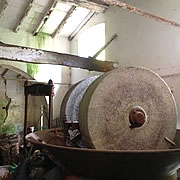
The working of the olives began with the frangitura (the breaking). The breaker consists of a circular metal basin, raised from the floor, in which there are two large cylindrical millstones, with a diameter of 135cm, placed vertically and connected by a horizontal axle, joined to a central shaft.
This shaft, through a gearing system, was powered by a transmission shaft which was connected by a belt to the main drive shaft , operated in turn by the turbine. (See Drawing 4.) The millstones, placed in the basin, can be lowered or raised by a special device.
The accessories in the basin are: small paddles that agitate the olive paste, pushing it under the grinding stones and speeding up the process; the scrapers that keep the grind-stones clean and prevent them from slipping and the 'expulsion paddle' for the progressive unloading of the paste. A further paddle stops the olive paste from overflowing from the basin itself.
The stone olive breaker still remaining in the olive press was installed in 1953 and processed around two quintale of produce per hour; previously there was a machine with only one stone and this one ground approximately one quintale of olives per hour.
After milling, the olive paste was removed from the basin through an opening at the side and placed under the press. The paste was put into special coconut containers called fiscoli that, wetted with boiling water, were placed one on top of the other in the press. (In all, around 15 fiscoli for a total of one quintale of olive paste.)
The press was hydraulic: a pump (which no longer exists) connected by a belt to the main motor shaft, pumped the water into the piston, approximately 120cm long. The piston, situated in the lower part of the press, pushed up the fiscoli as it moved towards the fixed higher part of the press. The oil and water that came out of the fiscoli were collected in large wooden buckets; the oil that rose to the water surface was then removed with a ladle. This process allowed one to obtain around one quintale of oil per hour
This old-type press, still present in the oil press area, was working until 1948-49; there was also an identical press in the room which housed the cylinder mill. After 1949, a new press was installed, which worked 'cold', that is to say, without hot water and at much higher pressures. The capacity of this press was two quintales per hour. In this press, instead of fiscoli, filters were used, on which, through a dosatore (distributor ) a 1cm layer of olive paste was placed. The piston for this press had a diameter of approximately 35 cm and it worked hydraulically. The vegetable water and the oil were collected in a steel tank and then, with a pump, the liquid was taken to the separator where the oil and vegetable water were separated centrifugally.
In the cellar under the oil press, called inferno (hell), there was a tank to recover lower quality oil for lamps (olio lampante). Outside there is a tank which was used to decant the vegetable waters before pouring them into the river - it is now the plunge pool!